CyderVis User Guide
Setup
Connect and Receive Data in CyderVis
- In CyderVis, locate the CAN Interface input field.
- Verify that the interface name matches the one brought up in the previous step (default is
can0). - Click Start to begin receiving data from the CAN adapter.
If other devices are active on the bus, incoming CAN frames will begin streaming into CyderVis and appear in the viewing table.
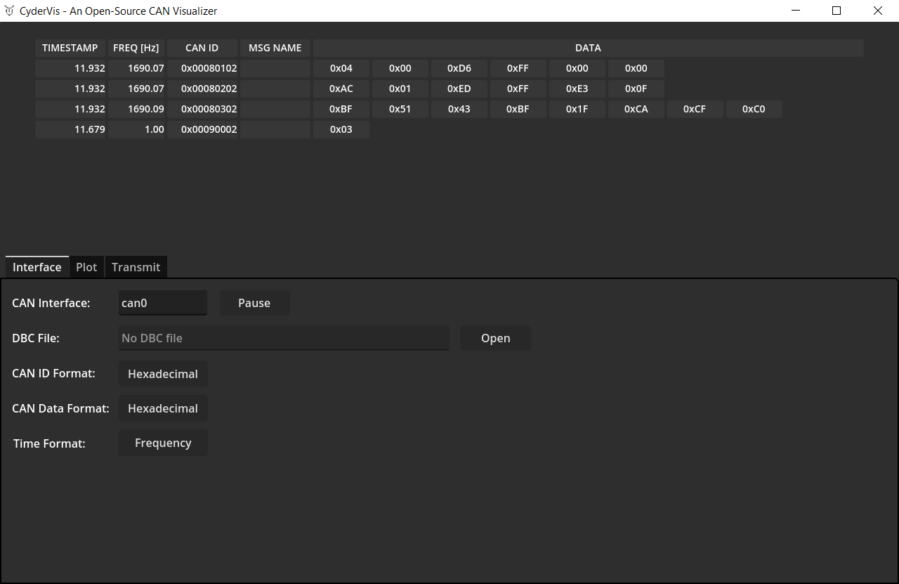
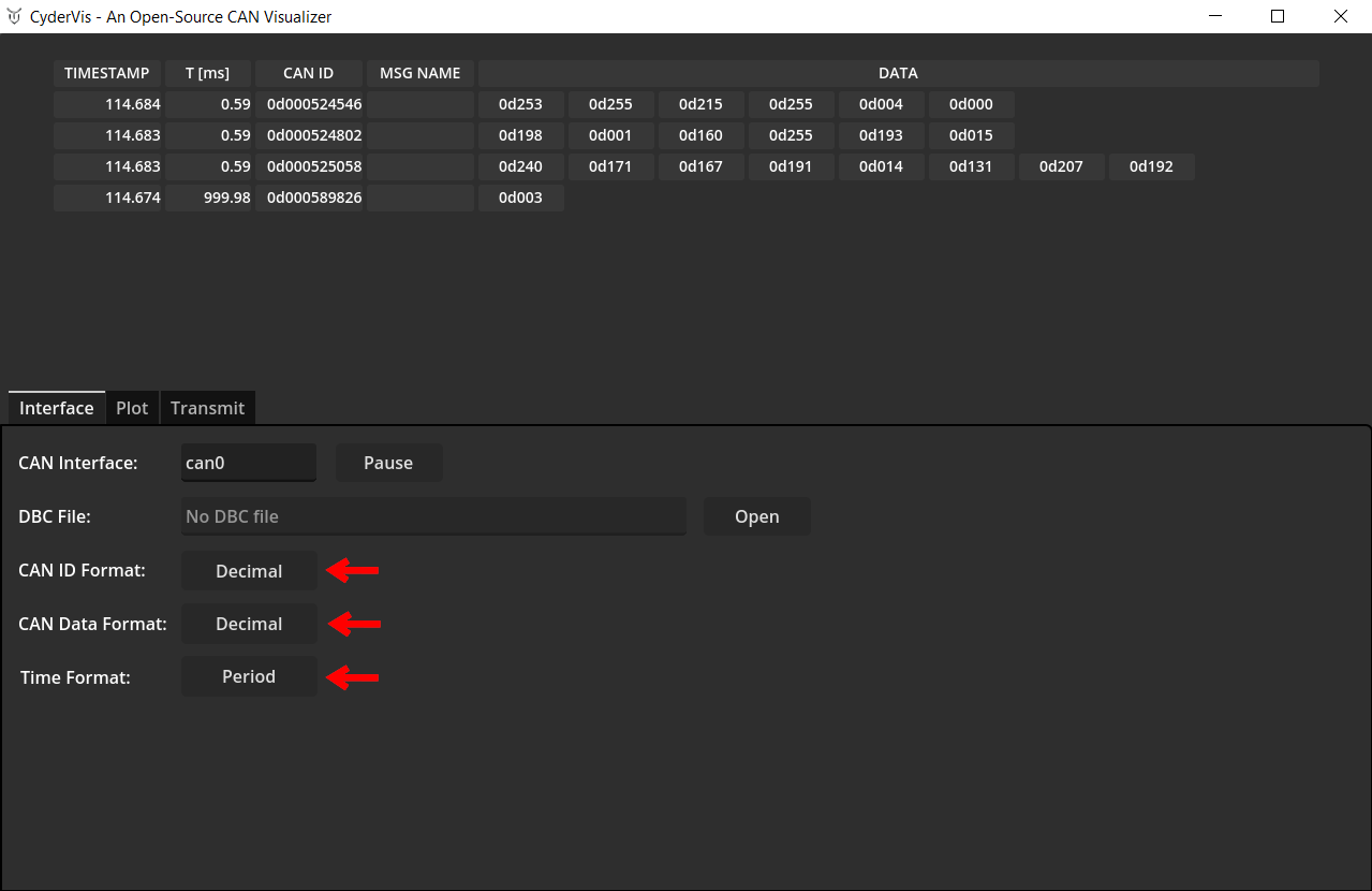
Adjust Display Options
Use the display option toggles to customize how CAN data is displayed.
These toggles control message formatting and visualization preferences.
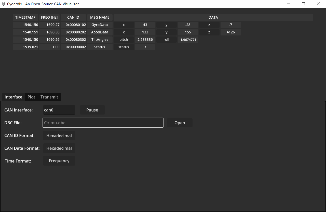
Load a .dbc File to Decode Frames
A DBC file defines how to decode CAN frames into human-readable signals.
You can learn more about the DBC format here:
https://docs.openvehicles.com/en/latest/components/vehicle_dbc/docs/dbc-primer.html
We provide example .dbc files for Cyder products at:
https://github.com/cyborg-dynamics-engineering/cyder-vis/tree/main/gdextension_can_io/examples
To load a .dbc file:
- Click Open next to the DBC File dialog.
- Select your
.dbcfile. - Once loaded, decoded frames will automatically appear in the viewing table.
Plotting Decoded Data
- Open the Plot tab.
- Click on any decoded variable name in the viewing table to toggle it on or off in the plot view.
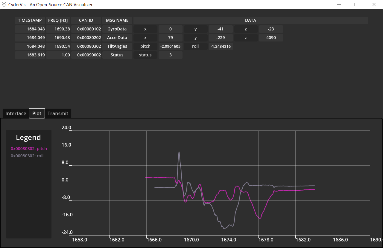
💡 Note:
Data must be decoded using a .dbc file to enable plotting.
Step 7: Transmitting Frames
- Open the Transmit tab.
- Press 'Add New' to create a new message.
- Fill out the Cycle Time, Frame ID and Data fields.
- For extended IDs, select the EXT ID checkbox.
- Click the 'Send' checkbox to begin transmitting.
💡 Notes:
- A Cycle Time of
0designates a one-shot message — it sends once each time you click the Send checkbox.- Messages cannot be edited whilst sending.
Troubleshooting
- CyderVis doesn’t connect:
Ensure thecanserveris running and the interface name matches (e.g.,can0).